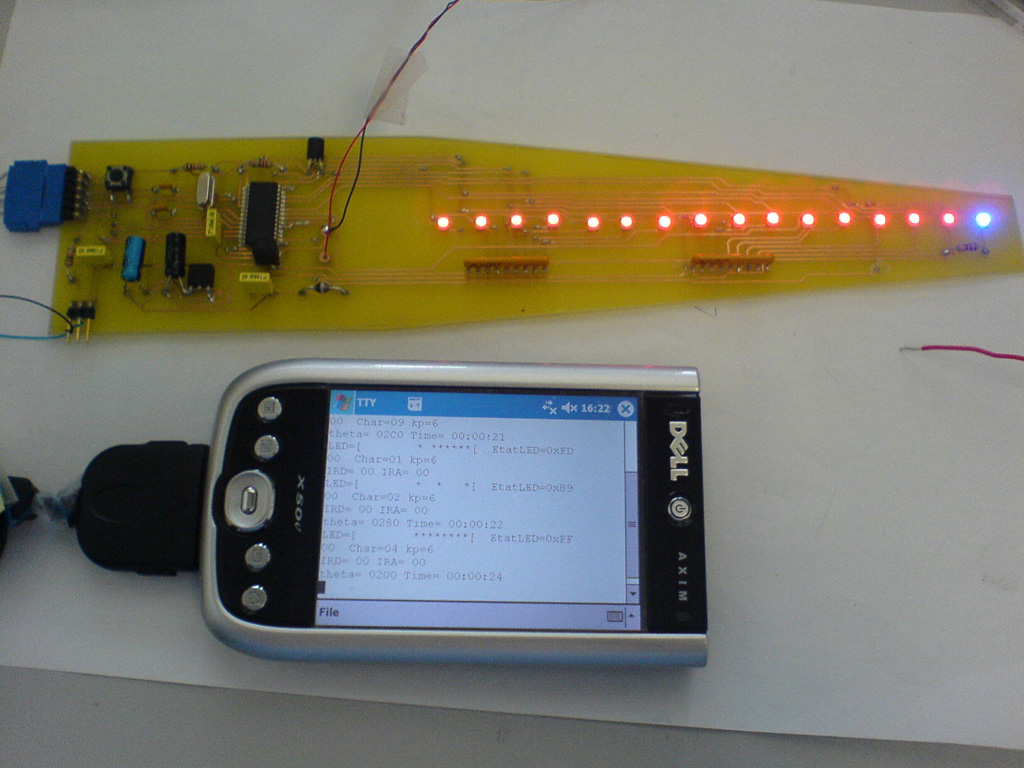
//-----------------------------------------------------------------------------
// Propellor Clock
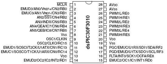
// dsPIC 30F3010
// L. BAGHLI 03/02/2007
// version actuelle : beta Quartz=10Mhz,
// IC2 repère un aimant tournant et calcule la Ts (Timer2)
// Timer1 ttes les 100 us allume le diodes en fonction de la position
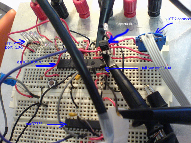
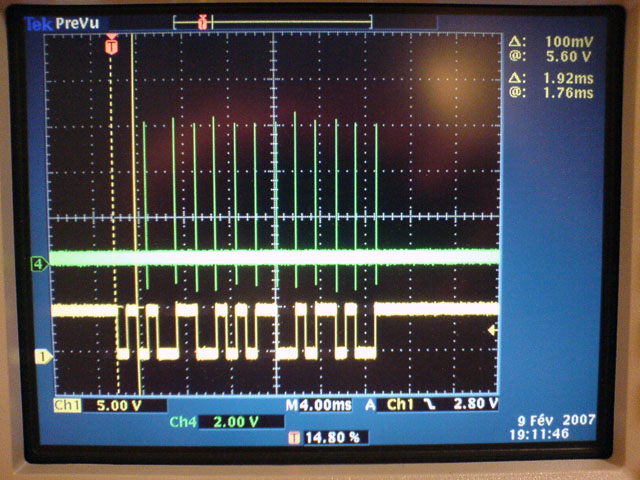
// v0.11 09/02/2007 prise en compte sur IC2/RD0 de l'entrée IR du 1838
// decodage de la trame RC5 en cours
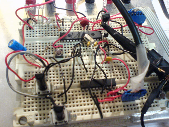
// MAX3233E pour envoyer les données de deboggage à un terminal RS232 via UART1
//-----------------------------------------------------------------------------
#include "p30F3010.h"
//Configuration bits
_FOSC(CSW_FSCM_OFF & XT_PLL8); //10Mhz *8 = 80 MHz /4 = 20 MIPS maxi pour ce pic
_FWDT(WDT_OFF);
_FBORPOR(PBOR_OFF & BORV_27 & PWRT_16 & MCLR_EN);
_FGS(CODE_PROT_OFF);
//-----------------------------------------------------------------------------
//Program Specific Constants
#define FCY 20000000 //Instruction cycle rate (Osc x PLL / 4) = 20 MIPS
#define T1Period 2000 // pour 100us à 20 MHz = T1Period = 2000=FCY*100us
#define tcntPRD 10000 // combien de fois pour ariver en 1s avec des pas de 100us : 10000
#define MILLISEC FCY/20000 // 1 mSec delay constant
// 11 LED differentes = 1 (en fait 6 en même tps) + 8 + 2 + 1 blue donc 12 Outputs
// LED bleue
#define LEDBlue PORTEbits.RE8 // la derniere (pour les secondes)
#define LED_E PORTE // 6 Leds
#define LED_B PORTB // 6 Leds
// IC1/RD0 et IC2/RD1 sont pour la mesure de l IR 1838 en codage RC5 et du top index du changement d etat du hall sensor SS40A
#define IR_receive PORTDbits.RD0 // InputIR module
#define TopIndex PORTDbits.RD1 // Input sends top index hall SS041 + aimant fixe.
void setup_ports(void);
void DelayNmSec(unsigned int N);
struct {
unsigned Running : 1;
unsigned CheckRX : 1;
unsigned SendTX : 1;
unsigned SendIR : 1;
unsigned Sendtheta : 1;
unsigned SendLED : 1;
unsigned IR_bit : 1; // bit value
unsigned IR_toggle : 1; // toggle on short pulse
unsigned IR_busy : 1; // receive in progress
unsigned IR_done : 1; // receive done
unsigned charinv : 1; // receive done
unsigned unused : 5;
} Flags;
// l angle theta est codé sur 16 bits.
unsigned int theta, dth, thcentre; // angle actuel et increment angulaire, centre du caractere à afficher
int Ts; // Periode de rotation (en unités Timer2)
unsigned int heure, heure1, heure2, min, min1, min2, sec, sec1, sec2, tcnt;
unsigned int Ref1, Ref2;
unsigned int thAigsec, thAigmin, thAigheure; // position des aiguilles
unsigned char Char2Disp, kp, EtatLEDchar; // etat des led pour les caracteres
unsigned int EtatLED; // etat des led sur 16 bits, LSB centre, MSB péripherie
int itmp;
// 65536/60 et 65536/12
#define c65536_60 1092
#define c65536_12 5461
// thc=M_PI/8;
// kth=5/M_PI;
// thsec1=M_PI*0.5/8;
// thsec2=M_PI*15.5/8;
// thmin1=M_PI*6/8+thc*0;
// thmin2=M_PI*6/8+thc*1;
// thcolon=M_PI;
// thh1=M_PI*6/8+thc*3;
// thh2=M_PI*6/8+thc*4;
#define thc 0x1000
#define thc_2 0x0800
#define kth 0.000152587890625
#define thsec1 0x0800
#define thsec2 0xF800
#define thmin1 0x6000
#define thmin2 0x7000
#define thcolon 0x8000
#define thheure1 0x9000
#define thheure2 0xA000
// angle de 2° pour la largeur des aiguilles
#define th2deg 0x016C
// code des caractères inversés
unsigned char invNumber[]={
0, 0, 0, 126, 129, 129, 129, 126, // 0 inversé encore une fois
0, 0, 0, 128, 130, 130, 253, 128, // 1
0, 0, 0, 194, 161, 145, 137, 134, // 2
0, 0, 0, 66, 129, 137, 137, 118, // 3
0, 32, 48, 40, 36, 34, 255, 32, // 4
0, 0, 0, 79, 129, 137, 137, 113, // 5
0, 0, 0, 124, 138, 137, 137, 112, // 6
0, 0, 0, 1, 193, 49, 13, 3, // 7
0, 0, 0, 118, 137, 137, 137, 118, // 8
0, 0, 0, 14, 145, 145, 81, 62, // 9
0, 0, 0, 0, 0, 102, 0, 0}; // :
// IR code -------------------------------------------
unsigned char IR_time; // count bit time
unsigned int IR_tmp; // shift bits in
unsigned int IR_CodeFull; // store result
unsigned char IR_CodeAddy, IR_CodeData;
#define PULSE1_2 (unsigned char)(8 * 1.5 + 1)
#define PULSE2MAX (unsigned char)(8 * 2.5 + 1)
// RS232 -------------------------------------------
unsigned char *TXPtr;
unsigned char *RXPtr;
void InitUART(void);
void SendMsg(void);
#define CR 0x0D
#define LF 0x0A
#define BAUD 19200
#define OffsetIRCodeData 5 // offset in OutData : position de la val de IRCodeData
#define OffsetIRCodeAddy 13 // offset in OutData : position de la val de IRCodeAddy
unsigned char InData[] = {"000000"};
unsigned char OutData[] = {"IRD= 00 IRA= 00\r\n"};
#define Offsettheta 7 // offset in OutData : position de la val de theta
#define OffsetTime 18 // offset in OutData : position de la val de Time
unsigned char OutTheta[] = {"theta= 0000 Time= 00:00:00\r\n"};
// offset in OutEtatLed
#define OffsetLED 5
#define OffsetEtatLED 34
#define OffsetChar 45
#define Offsetkp 51
unsigned char OutEtatLed[] = {"LED=[0123456789ABCDEF[ EtatLED=0xXXXX Char=XX kp=X\r\n"};
int SeqComm; // ttes les 0.5 s
#define SeqCommMax 5000
//debug bad #define SeqCommMax 2000
// -------------------------------------------
//-----------------------------------------------------------------------------
// Initialise variables
//-----------------------------------------------------------------------------
void InitVar(void)
{
Flags.Running=0;
tcnt=0;
heure=0; heure1=0; heure2=0;
min=0; min1=0; min2=0;
sec=0; sec1=0; sec2=0;
Flags.IR_done=0; Flags.IR_busy=0;
Flags.IR_bit=1;
Flags.SendIR = 0; // clear 3 flags RS232
Flags.Sendtheta = 0;
Flags.SendLED = 0;
}
//-----------------------------------------------------------------------------
// Setup ports
//-----------------------------------------------------------------------------
void setup_ports(void)
{
// Clear All Ports Prior to defining I/O
// ADPCFG = 0xFFFF; // all PORTB = Digital(1), no analog
PORTB=0; //Initialize LED pin data to off state
PORTC=0;
PORTD=0;
PORTE=0;
// Now set pin direction registers
//debug_____________________________________________________________________
// temporaire pour lire la valeur de theta à l aide des potars AN4 et AN5 sur ch3 et ch4
// TRISB = 0xFF00; // RB0-5 output LED
TRISB = 0xFFF0; // RB0-3 output LED, RB4, 5 input ADC AN4 et AN5
TRISC = 0xDFFF; // C13 TX out, C14 RX in, le reste : input / Unused
TRISD = 0xFFFF; // RD0 input : Topindex, RD1 input : IR_receive
TRISE = 0x0000; // RE0-8 Output LED
TRISF = 0xFFFF; // RFx not used (input)
//debug_____________________________________________________________________
// temporaire pour lire la valeur de theta à l aide des potars AN4 et AN5 sur ch3 et ch4
ADPCFG = 0xFFCF; // all PORTB = Digital(1) ;RB4 et RB5 = analog(0) ie 1100 1111
ADCON1 = 0x000F; // Clearing SAMP bit SOC, 4 ch simultanés, ADC Off for configuring
ADCON2 = 0x0200; // simulataneous sample 4 channels, ADC INTerrupt à chaque EOC=100 us
ADCHS = 0x0020; // AN4/RB4 Ch2 Ref1, AN5/RB5 Ch3 Ref2
ADCON3 = 0x0080; // Tad = internal RC (4uS)
ADCON1bits.ADON = 1; // turn ADC ON
// fin debug temporaire_____________________________________________________
}
//-----------------------------------------------------------------------------
// intitialise timer 1 et l interruption
//-----------------------------------------------------------------------------
void initTimer_CNx(void)
{
// Timer1 pour l ISR des 100 us
T1CON = 0; // ensure Timer 1 is in reset state, internal timer clock Fosc/4, no prescale
TMR1 = 0; // RAZ Timer1
IFS0bits.T1IF = 0; // reset Timer 1 interrupt flag
IPC0bits.T1IP = 4; // set Timer1 interrupt priority level to 4
IEC0bits.T1IE = 1; // enable Timer 1 interrupt
PR1 = T1Period; // set Timer 1 period register
// Timer2 pour compter Ts entre 2 index
T2CON = 0x0010; // ensure Timer 1 is in reset state, internal timer clock Fosc/4, prescale 1:8
// ie 100 tr/s donne Ts=20e6*0.01/8 = 25000 = 0x61A8
TMR2 = 0; // RAZ Timer2
PR2 = 0xFFFF; // set Timer 2 period register maximum, RAZ sur index
// ICN2 enclenché sur Timer2, on rising edge pour la sonde Hall d index
IC2CON = 0x0083;
IFS0bits.IC2IF = 0; // Clear IF bit
IPC1bits.IC2IP = 3; // assigning Interrupt Priority to IPC Register
IEC0bits.IC2IE = 1; // assiging Interrupt Enable
T2CONbits.TON = 1; // enable Timer 2 and start the count
T1CONbits.TON = 1; // enable Timer 1 and start the count
}
//---------------------------------------------------------------------
// Check si on est sur une aiguille
int InAiguille(unsigned int th1, unsigned int th2)
{
if (th1-th2<=th2deg && th1-th2>=0) return 1; //2 degrés
else return 0;
}
//---------------------------------------------------------------------------
// Check si on est sur un caractere
int InCaractere(unsigned int th1, unsigned int th2)
{
unsigned int res;
res=th1-th2;
if (th1 <th2) res=-res;
if ( res<thc_2) return 1; //th est ds le carcatere
else return 0;
}
//---------------------------------------------------------------------
// Timer1 interrupt fait le calcul et l allumage des LED
// ISR toutes les 100 us
//---------------------------------------------------------------------
void __attribute__((__interrupt__)) _T1Interrupt( void )
{
//PORTEbits.RE8=1; // InterruptLED=1;
IFS0bits.T1IF = 0;
// theta+=dth; // new position
// if (theta> depasse 2pi) alors on fait quoi ?
//debug_____________________________________________________________________
// temporaire pour lire la valeur de theta à l aide des potars AN4 et AN5 sur ch3 et ch4
ADCON1bits.SAMP = 0; // start conversion
while(!ADCON1bits.DONE) {} // attend la fin
Ref1=ADCBUF2;
Ref2=ADCBUF3;
// debug
// PORTE=Ref1>>4;
// if (Ref1>512) PORTEbits.RE8=1;
// else PORTEbits.RE8=0;
//___
// dummy read adcbuf 0 et 1 ?
// debug
// theta=Ref1<<6;
theta=(Ref1<<6) + (Ref2<<2); // donne une position fictive des diodes theta=(Ref1<<6) + (Ref2<<2);
// theta=Ref1; // donne une position fictive des diodes
if (++tcnt>=tcntPRD)
{
tcnt=0;
sec++;
if (++sec1==10)
{
sec1=0;
if (++sec2==6)
{
sec=0;
sec2=0;
min++;
if (++min1==10)
{
min1=0;
if (++min2==6)
{
min=0;
min2=0;
heure1++;
if (++heure==24)
{
heure1=0;
heure2=0;
}
else if (heure1==10) // n atteintt pas plus de 23 h !
{
heure1=0;
heure2++;
}
}
}
}
}
// comme l'heure hh:mm:ss a changé => calcule la nouvelle position des aiguilles
thAigsec=c65536_60*sec;
thAigmin=c65536_60*min;
itmp=heure-12;
if (itmp<0) thAigheure=c65536_12*heure;
else thAigheure=c65536_12*itmp;
}
// fin debug temporaire_____________________________________________________
// utilisation du theta et de l heure !
Char2Disp=22; // ie pas ds un caractere
Flags.charinv=0;
if (InCaractere(theta, thsec1)) {Char2Disp=sec1; thcentre=thsec1; Flags.charinv=1;}
if (InCaractere(theta, thsec2)) {Char2Disp=sec2; thcentre=thsec2; Flags.charinv=1;}
if (InCaractere(theta, thmin1)) {Char2Disp=min1; thcentre=thmin1; }
if (InCaractere(theta, thmin2)) {Char2Disp=min2; thcentre=thmin2; }
if (InCaractere(theta, thheure1)) {Char2Disp=heure1; thcentre=thheure1; }
if (InCaractere(theta, thheure2)) {Char2Disp=heure2; thcentre=thheure2; }
if (InCaractere(theta, thcolon)) {Char2Disp=10; thcentre=thcolon; } // :
// calcule l'etat des LED
EtatLED=0;
if (InAiguille(theta,thAigheure)) EtatLED |=0x001F;
if (InAiguille(theta,thAigmin)) EtatLED |=0x007F;
if (InAiguille(theta,thAigsec)) EtatLED |=0x0080;
EtatLEDchar=0;
if (Char2Disp!=22)
{
kp=(theta-thcentre+thc_2)>>9; // de theta vers pixel index : 0x1000 -> 8 ie divisé par 0x200
if (Flags.charinv) kp=7-kp;
if (kp>7) kp=7;
EtatLEDchar=invNumber[(Char2Disp<<3)+kp];
EtatLED |= EtatLEDchar<<8; // affiche le caractère vers l'extrémité, loin du centre de rotation
}
// allume les LED
// debug
// ne touche pas à RE8
unsigned int etatR8=PORTE & 0x100;
PORTE=(EtatLED>>8 )& 0x3F | etatR8; // 6 LED actuellement + 1 de controle/oscillo
// decode trame IR suivant RC5
if (!IR_receive==Flags.IR_bit){ // change detect
Flags.IR_bit = ~Flags.IR_bit; // store new state
if( Flags.IR_busy == 0 ) {
if( Flags.IR_bit == 1 ){ // start pulse detect
Flags.IR_busy = 1;
IR_tmp = 1; // == 0x2000 after 13 shift
Flags.IR_toggle = 1;
}
}
else {
Flags.IR_toggle = ~Flags.IR_toggle; // skip every second change
if( Flags.IR_toggle || IR_time < PULSE1_2 ){
PORTEbits.RE8=1;
Flags.IR_toggle = 1; // false on next pulse
IR_tmp <<= 1; // shift
if( Flags.IR_bit ) IR_tmp |= 1; // add new bit
if( IR_tmp & 0x2000 ){ // after shifted 13 times
IR_CodeFull = IR_tmp;
Flags.IR_busy = 0;
Flags.IR_done = 1;
IR_CodeAddy=IR_CodeFull>>6 & 0x1F;
IR_CodeData=IR_CodeFull & 0x3F;
}
PORTEbits.RE8=0;
}
}
IR_time = PULSE2MAX;
}
else {
if (--IR_time==0 ) // if no change, count down
Flags.IR_busy = 0; // timeout
}
// communication dsPIC -> PC
if (!--SeqComm) {
SeqComm=SeqCommMax;
// uniquement si nouvelle donnée : if (IR_done) Flags.SendIR=1;
Flags.SendIR=1;
Flags.Sendtheta=1;
Flags.SendLED=1;
}
//PORTEbits.RE8=0; // InterruptLED=0;
}
//---------------------------------------------------------------------
// ICN2 interrupt : passage devant l index (aimant) alors mesure du chrono et RAZ
//---------------------------------------------------------------------
void __attribute__((__interrupt__)) _IC2Interrupt( void )
{
IFS0bits.IC2IF = 0;
TMR2 = 0; // RAZ Timer2
theta=0; // la position aussi
if (IC1CONbits.ICBNE) Ts= IC2BUF; // reads the input capture buffer
// calcule l incrément dth correspondant à 100 us
// il y a N increment en 0.01s : N = 0.01s/100us = Ts*8/(100e-6*20e6) = 65536/dth
// dth=65536*2000/8/Ts
//debug
// dth=8192*T1Period/Ts;
}
//---------------------------------------------------------------------
// Below are the interrupt vectors for the serial receive and transmit
//---------------------------------------------------------------------
void __attribute__((__interrupt__)) _U1TXInterrupt(void)
{
IFS0bits.U1TXIF = 0; // clear interrupt flag
}
//---------------------------------------------------------------------
void __attribute__((__interrupt__)) _U1RXInterrupt(void)
{
IFS0bits.U1RXIF = 0; // clear interrupt flag
*RXPtr = U1RXREG;
if (*RXPtr == CR)
{Flags.CheckRX = 1;
RXPtr = &InData[0];}
else *RXPtr++;
}
//------------------------------------------------------------------------
// Transmission over serial
void InitUART(void)
{
// Initialize the UART1 for BAUD = 19,200
U1MODE = 0x8400; // enable + alternate pins
// U1MODE = 0x8000; // enable + normal pins
U1STA = 0x0000;
U1BRG = ((FCY/16)/BAUD) - 1; // set baud to 19200
IEC0bits.U1RXIE = 1; // enable RX interrupt
RXPtr = &InData[0]; // point to first char in receive buffer
Flags.CheckRX = 0; // clear rx and tx flags
Flags.SendTX = 0;
U1STAbits.UTXEN = 1; // Initiate transmission
SeqComm=SeqCommMax;
}
//------------------------------------------------------------------------
// Sendfs sends the IRcode (Data & Addy) information on the uart at 19200 baud
void SendIRcode()
{
unsigned int k;
unsigned char c;
// Codage ASCII de la donnée
k = IR_CodeData;
c = k/10;
if (c > 0)
k = k - c*10;
OutData[OffsetIRCodeData] = (c + 0x30);
OutData[OffsetIRCodeData+1] = (char)(k + 0x30);
k = IR_CodeAddy; //format à revoir ....
c = k/10;
if (c > 0)
k = k - c*10;
OutData[OffsetIRCodeAddy] = (c + 0x30);
OutData[OffsetIRCodeAddy+1] = (char)(k + 0x30);
TXPtr = &OutData[0];
SendMsg();
}
//------------------------------------------------------------------------
// Sendfs sends the theta information on the uart at 19200 baud
void Sendthetacode()
{
unsigned int k;
unsigned char c;
// Codage ASCII de la donnée hexa
k = theta;
c=k & 0x000F;
if (c<=9) c+=0x30;
else c+=0x37;
OutTheta[Offsettheta+3]=c;
c=k>>4 & 0x000F;
if (c<=9) c+=0x30;
else c+=0x37;
OutTheta[Offsettheta+2]=c;
c=k>>8 & 0x000F;
if (c<=9) c+=0x30;
else c+=0x37;
OutTheta[Offsettheta+1]=c;
c=k>>12 & 0x000F;
if (c<=9) c+=0x30;
else c+=0x37;
OutTheta[Offsettheta]=c;
// codage ASCII de l heure
OutTheta[OffsetTime]= (heure2 + 0x30);
OutTheta[OffsetTime+1]=(heure1 + 0x30);
OutTheta[OffsetTime+3]=(min2 + 0x30);
OutTheta[OffsetTime+4]=(min1 + 0x30);
OutTheta[OffsetTime+6]=(sec2 + 0x30);
OutTheta[OffsetTime+7]=(sec1 + 0x30);
TXPtr = &OutTheta[0];
SendMsg();
}//------------------------------------------------------------------------
// Sendfs sends the LED information on the uart at 19200 baud
void SendLEDcode()
{
unsigned int k;
unsigned char c;
// Codage ASCII de la donnée hexa
for (k=0; k<16; k++)
if ((EtatLED>>k)&1 == 1) OutEtatLed[OffsetLED+k]=0x2A;
else OutEtatLed[OffsetLED+k]=0x20;
k = EtatLED;
c=k & 0x000F;
if (c<=9) c+=0x30;
else c+=0x37;
OutEtatLed[OffsetEtatLED+3]=c;
c=k>>4 & 0x000F;
if (c<=9) c+=0x30;
else c+=0x37;
OutEtatLed[OffsetEtatLED+2]=c;
c=k>>8 & 0x000F;
if (c<=9) c+=0x30;
else c+=0x37;
OutEtatLed[OffsetEtatLED+1]=c;
c=k>>12 & 0x000F;
if (c<=9) c+=0x30;
else c+=0x37;
OutEtatLed[OffsetEtatLED]=c;
// Char
k = Char2Disp;
c = k/10;
if (c > 0)
k = k - c*10;
OutEtatLed[OffsetChar] = (c + 0x30);
OutEtatLed[OffsetChar+1] = (char)(k + 0x30);
// kp
OutEtatLed[Offsetkp] = (kp + 0x30);
TXPtr = &OutEtatLed[0];
SendMsg();
}
//-----------------------------------------------------------------------------
void SendMsg(void)
{
while (*TXPtr)
{
while (U1STAbits.UTXBF);
U1TXREG = *TXPtr++;
}
}
//-----------------------------------------------------------------------------
//Main routine
int main(void)
{
setup_ports();
InitVar();
InitUART();
initTimer_CNx();
while(1)
{
if (Flags.SendIR)
{
SendIRcode(); // send present fs serially
Flags.SendIR = 0; // clear flag
}
if (Flags.Sendtheta)
{
Sendthetacode(); // send present fs serially
Flags.Sendtheta = 0; // clear flag
}
if (Flags.SendLED)
{
SendLEDcode(); // send present fs serially
Flags.SendLED = 0; // clear flag
}
} // end of while (1)
} // end of main
//=============================================================================
//Error traps
//-----------------------------------------------------------------------------
//Oscillator Fail Error trap routine
void _ISR _OscillatorFail(void)
{
while(1); //Wait forever
}
//-----------------------------------------------------------------------------
//Address Error trap routine
void _ISR _AddressError(void)
{
while(1); //Wait forever
}
//-----------------------------------------------------------------------------
//Stack Error trap routine
void _ISR _StackError(void)
{
while(1); //Wait forever
}
//-----------------------------------------------------------------------------
//Math (Arithmetic) Error trap routine
void _ISR _MathError(void)
{
while(1); //Wait forever
}
//---------------------------------------------------------------------
// This is a generic 1ms delay routine to give a 1mS to 65.5 Seconds delay
// For N = 1 the delay is 1 mS, for N = 65535 the delay is 65,535 mS.
// Note that FCY is used in the computation. Please make the necessary
// Changes(PLLx4 or PLLx8 etc) to compute the right FCY as in the define
// statement above.
//---------------------------------------------------------------------
void DelayNmSec(unsigned int N)
{
unsigned int j;
while(N--)
for(j=0;j < MILLISEC;j++);
}
//---------------------------------------------------------------------
